


Index to technical notes/technical terms
Click to make your choice from the following item.
![]()
Technical terms of NTC thermistors
- 3. Resistance-temperature characteristics
- 4. Zero load resistance
- 5. B constant
- 6. Zero load resistance-temperature coefficient/Dissipation constant
- 7. Thermal time constant
- 8. Category temp. range/max. allowable capacitance
- 9. Rated wattage
- 10. Specifications of pictorial symbols and letter symbols
- 11. Temperature
![]()
1. Thermistors/Varistors
NTC thermistors, among thermally sensitive resistors, are the generic name of thermistors with a negative temperature coefficient (Negative Temperature Coefficient thermistors) where resistance declines as temperature rises. NTC thermistors are used as temperature sensors in extended application fields including temperature measurement, temperature compensation and assembly into equipment.
PTC thermistors are semi-conductors electrically conductive with barium titanate (BaTiO3) serving as the main ingredient and with a subtle amount of rare earth contained.
Characterized by the property that resistance sharply increases due to phase transition occurring at a certain temperature called the Curie point, PTC thermistors are in use in many fields as current limiting elements, constant temperature heating element or temperature sensors.
MNR varistors have distinguished voltage non-linearity and withstand high surges and thus produce a great effect for lightning surge and over-voltage.
OHIZUMI’s devices are available in configurations and characteristics that suit customers’ needs.
Press here to return to the top of this page.
2. Thermistor assemblies
OHIZUMI’s thermistor assemblies are temperature sensors assembled of highly accurate and reliable thermistors to specific customer requirements.
Thermistor assemblies intended for household and housing can be found in every appliance if they are related to “temperatures” in our everyday life.
They are most commonly playing a key role in invisible places to make our life more convenient and comfortable.
Our thermistor assembles have earned a high reputation from our customers who adopted them for needs for temperature measurement in vehicles, as well as for their automotive air conditioners for provision of spaces of greater comfort and for engine control for realization of ideal wattage sources.
OHIZUMI’s thermistor assembles are provided on a custom-tailoring basis so that customers’ needs can be 100% met.
Press here to return to the top of this page.
3. Resistance-temperature characteristics
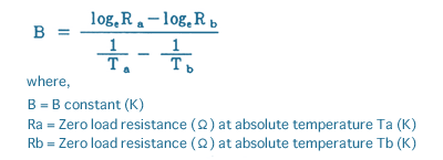
Resistance-temperature characteristics are the relationship between zero load resistance and element temperature. Resistance-temperature characteristics are available from actual measurements. However, they can be approximately obtained via the following formula if the B constant is known:
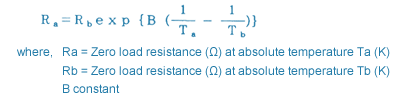
The above formula indicates that the logarithm of zero load resistance and the inverse number of the thermodynamic temperature are in a linear relationship.
An example of resistance-temperature characteristics is shown in Fig. 3.1.1.
Press here to return to the top of this page.
4. Zero load resistance
Thermistor resistance is measured in a constant ambient temperature. However, the effect of self-wattage generation due to the current flowing in the thermistor being measured makes it impossible to measure logically accurate resistance. So, measurement is taken under conditions where self-heat dissipation may be negligible.
Zero load resistance is defined to be the DC resistance of a thermistor measured in the specified temperature with sufficiently low wattage consumption (wattage smaller than 1/20 of the dissipation constant) ("zero load") where the resistance change due to self-heat dissipation is negligible when compared to the overall error in measurements.
And, zero load resistance representative of the specification value is called the nominal zero load resistance. Unless otherwise specified, the value at 25℃ ambient temperature is the nominal zero load resistance.
Recommended tolerances for the nominal zero load resistance are defined in JIS C 2570-1998 (Directly heated negative temperature coefficient thermistors -- Part 1: Generic specification) as illustrated in Table 3.1.1.1. So, if the resistance tolerance is the same, the higher the B constant, the more accurate the resistance tolerance.
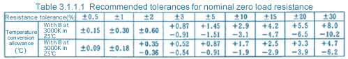
For the figures in the above table, “tolerance/α= zero load resistance temperature coefficient” been used (αT from 3.1.3). Actual calculations should produce the same figures at both the + and - sides, but, in the above table, figures are edited to a small extent.
Although designing work will be easier as the tolerance for the nominal zero load resistance becomes smaller, thermistor prices will rise as tolerances become smaller. Circuitry, therefore, should be designed with tolerances of thermistors as widely as feasible.
Press here to return to the top of this page.
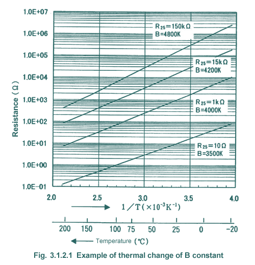
5. B constant
B constant is defined to be a constant which indicates magnitude of resistance change obtained from two arbitrarily chosen points of resistance-temperature characteristics, and 1S expressed as follows:
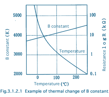
Although B constant is a constant, it actually is not. It increases slightly as temperature goes up, as shown in Fig. 3.1.2.1. To determine a B constant, temperatures Ta and Tb at two different points are necessary. Temperatures are typically 25℃ and 85℃ but they may be 25℃ and 50℃, or 100℃ and 200℃ depending upon applications. Attention must be paid to this fact when encountering this problem. A common practice to clearly identify these Ta and Tb temperatures is to express B constants as Ba/b.
If the temperature difference between two points, Ta and Tb, is lower than 10℃, the error of the B constant due to the error in measured temperature will become bigger. On the other hand, if the difference exceeds 100℃, then the difference from B constant at the temperature of use is considered to be excessive. Thus, the most desirable temperature difference between Ta and Tb may be said to be between 50℃ and 100℃.
The B constant representing the specification value is called the nominal B constant. Its recommended tolerances are defined in JIS C 2570-1998 as follows:
±0.5%, ±1%, ±2%, ±3%, ±5%, ±10% and ±15%
Specific resistance and B constant of thermistors are determined by their ingredients. Generally, as B constant becomes bigger, the bigger zero load resistance tends to be if the thermistor configuration remains the same. This means that replacement of a thermistor will not always allow arbitrary selection of combination of B constant and zero load resistance, if the configuration is the same.
Press here to return to the top of this page.
6. Zero load resistance-temp. coefficient/dissipation constant
Zero load resistance-temperature coefficient is defined to be a coefficient indicating rates of changes of zero load resistance per 1℃ at an arbitrarily selected temperature T, and expressed by the following formula:
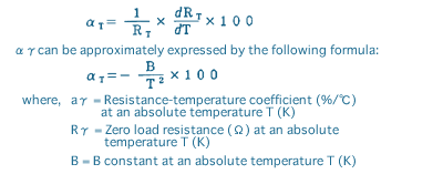
As indicated by the above formula, zero load resistance-temperature coefficients (αT) greatly vary depending upon temperatures, especially at a low temperature region. Use of this zero load resistance-temperature coefficient (αT) is convenient for intuitive evaluation of temperature gradient in the vicinity of a certain temperature.
Although there are two performance rating indices ofαT and B constant for temperature gradient of zero load resistance, use of B constant is a common practice for comparison of only the magnitude of temperature gradient.
Dissipation constant is a constant which indicates wattage necessary to have the temperature of thermistors to rise by 1℃ by its self-heat dissipation in stable temperature.
It can be obtained in units of mW/℃ if the wattage consumption of a thermistor is divided by the magnitude of temperature rise of the element.
Dissipation constant will be determined by the surface area, structure, materials of the protector and environmental conditions (e.g. medium and its flow rate) of thermistors. The relationship of electrical energy to be supplied to thermistors in a heat equilibrium state with emitted thermal energy can be approximately expressed by the following formula:
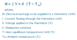
The above formula does not contain a thermal radiation term. It would be better to consider that dissipation factorδcan be regarded as constant when the ambient temperature is 100℃. max.
Press here to return to the top of this page.
7. Thermal time constant
A thermal time constant (γ) is defined to be a constant indicating the degree of thermal responsiveness of a thermistor.
No thermistor operation can be free of a time lag because the thermistor’s every operation is a thermal phenomenon.
Thermal time constant (γ) is the period of time necessary for a thermistor temperature to change by 63.2% when wattage is applied to the thermistor and an abrupt change is made to it from a heat equilibrium state to a zero load state.
The following formula is established for the temperature change of a thermistor exposed to an ambient temperature of TA (TA<Tb) with heat equilibrium temperature Tb of a loaded thermistor set under a zero load state, if Tb is no higher than 100℃ where the effect of thermal radiation can be neglected.
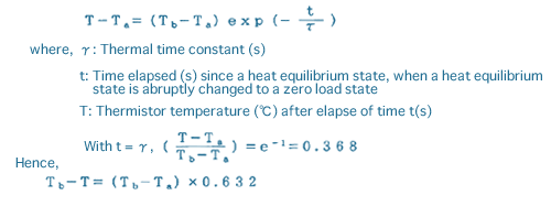
That is, the time period during which temperature effectiveness (Tb-T) becomes 63.2% of the temperature width (Tb-Ta) is taken as γ.
With the thermistor ambient temperature abruptly changed as experienced above, the thermal time constant, read when load current to a thermistor is abruptly changed from a non-zero-load condition to a zero-load condition, is cited as the thermal time constant (γi) by self-heat dissipation.
Under a zero-load condition, a thermal time constant, when the thermistor ambient temperature is abruptly changed, is cited as a “thermal time constant (γa) due to the change of the ambient temperature”.
Due to the fact that the thermal time constant of these two types may occasionally differ substantially depending on the structure and protector, the type of thermal time constant being discussed needs to be identified.
Please note that there are two types of thermal time constants of self-heat dissipation origin. One is a cooling time constant occurring when a thermistor is cooled down from a heated condition by reducing load current, and the other is a heating time constant transpiring when a thermistor is heated from a cooled condition to an over-heated condition by increasing the load current.
Press here to return to the top of this page.
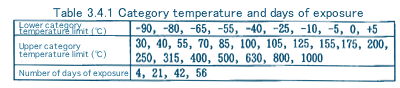
8. Category temperature range and maximum allowable capacitance
Category temperature range is defined to be the temperature range of thermistors where they can be used continuously with zero load.
Thermistor performance is guaranteed for this range of temperature by manufacturers.
Use must not deviate from such temperature ranges.
Attention must be paid to a fear that use of thermistors outside of this “category temperature range” may cause their rapid deterioration.
If thermistors self-heat, the ambient temperature where they will be used shall be after deduction of the rising temperature range due to the self-heat dissipation from the upper limit of the category temperature.
Category temperature range is defined generally by the upper and lower limits.
If use occurs mainly at low temperature with the high temperature side being within normal temperature, individual specifications may only define the lower temperature limit in place of the category temperature range, and vice versa.
Category temperatures are be defined in JIS C 2570-1998, as shown in Table 3.4.1 below:
Maximum allowable capacitance is defined to be the maximum capacitance of the capacitor which can be connected to a thermistor with an input of 100V AC. For input other than 100V AC, calculation needs to be performed based on the chargeable capacity of capacitors.
Press here to return to the top of this page.
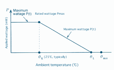
9. Rated wattage
Thermistors will heat by themselves as voltage is applied and reaches the ambient temperature-dependent heat equilibrium temperature. However, upper limits are defined as continually applicable wattage to deal with possible thermal runaway which may occur due to excessive wattage or possibly result in damage depending on the magnitude of self-heat dissipation.
Rated wattage is defined to be the maximum wattage that can be continually applied in a rated ambient temperature environment specified in an individual specification (typically 25℃), and expressed in units of milli watt (mW).
The maximum value of wattage that can be applied to thermistors continually in arbitrarily chosen ambient temperature is called the maximum wattage. When the ambient temperature is higher than the rated ambient temperature, the maximum wattage can be obtained from the following line connecting Point A and Point B. In this specific instance, Point A is where the wattage is set at zero at the temperature (θL) defined in the relevant individual specification under the upper category temperature limit (θmax), and point B is the rated wattage.
Press here to return to the top of this page.
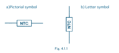
10. Specifications of pictorial symbols and letter symbols
“Pictorial symbols” and “letter symbols” for directly heated NTC thermistors are defined in JIS C 2570-1998 as shown in Fig. 4.1.1.
Press here to return to the top of this page.
11. Temperature
Temperature is defined as quantified sensations of coldness or warmth. There are three temperature systems for methods of quantification.
They are Fahrenheit (゚F), Celsius (゚C) and thermodynamic temperature (K = Kelvin).
The Fahrenheit system is said to be the distance from the temperature of a mixture of ice and ammonium chloride to the temperature of human bodies, divided into 96 sections.
The Celsius system is the temperature range formed by the freezing and boiling points of water and sub-divided equally into 100 sub-sections. The thermodynamic temperature system defines the triple point of water as 273.16K. The unit of this system is 1/273.16 of this triple point.
The relationship between Fahrenheit temperatures (t2) and the Celsius temperatures (t1) can be expressed by the following formulae 5.1 and 5.2.
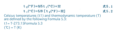
This formula indicates that the Celsius temperature unit is equal to the Kelvin unit of the thermodynamic temperature system. (Temperature difference is expressed in either Kelvin or Celsius.)
Thermodynamic temperature can be obtained from pressure ratios in an ideal condition, using an ideal gas. However, there can be no ideal gas or state. So, thermodynamic temperature is commonly obtained by trying to secure the true value by arranging the condition as close to an ideal as possible and making amendments as necessary.
Specifically, gas thermometers, sound-velocity thermometers, thermal noise thermometers or radiation thermometers are used.
A temperature unit should be standardized for international applications as with other units (such as length and weight).
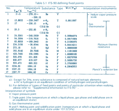
For standardization, a temperature unit and number of divisions must be determined. The standard currently used for temperatures is the “1990 international temperature scale” (ITS-90).
In Japan, it was enforced as a ministerial ordinance on Oct. 2, 1990.
Table 5.1 shows ITS-90 defining fixed points and interpolation instruments.